Installation Guide for Xterra Off road Light Brackets
Tools Required:
- T25 torx bit and driver
- Philips screwdriver
- Needle nose pliers
- Small flat head screwdriver
- 5/32” allen wrench
Separately purchased equipment:
- Deutsch DT Adapter wires (DT to 9006) for plug and play
- Diode Dynamics SS3 round pods
Disassembly of stock Pro-4X Off road light
- Remove the 6 rounded head shoulder bolts that hold the off road assembly to the Xterra
- T30 torx bit
- Note these bolts are attached to rivnuts and strip out relatively easily.
- I stripped one of mine and had to drill it out so be careful
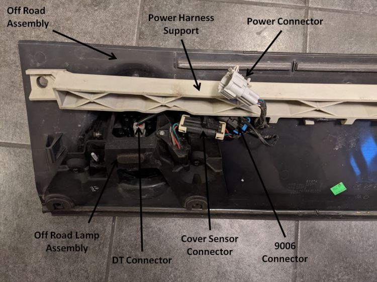
- Disconnect single power connect (Figure 1)
- Disconnect both harness connectors on each lamp assembly
- 9006 connector – There is a polarity to these plugs take note.
- Cover sensor connector
- Disconnect both harness connectors on each lamp assembly
- Remove the 3 screws holding the power harness support from off road assembly
- T25 torx bit
- Remove the 3 screws holding each of the off road lamp assemblies
- T25 torx bit

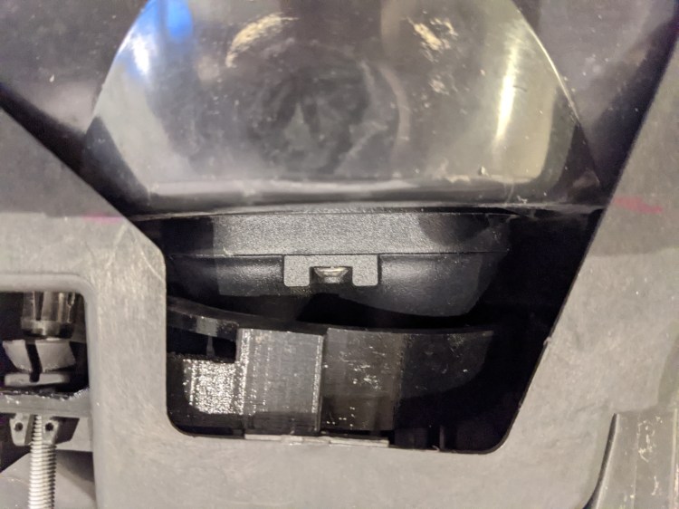
- Remove vertical adjustment bolt (Figure 2)
- Philips screwdriver
- Rotate adjustment bolt counterclockwise to locate the two locking lobes holding the adjustment bolt in off road lamp assembly
- Compress the lobes using a needle nose pliers
- Leaving a 1/8-3/16” gap between the edge of the lobes and the off road lamp assembly
- Push lobe assembly through hole allowing the adjustment bolt to be removed from off road lamp assembly when backed out
- Back out adjustment bolt until bolt is free from assembly
- Remove vertical adjustment nut from off road lamp assembly by pinching smaller end to allow it to release from off road lamp
- Remove off road lamp from lamp assembly
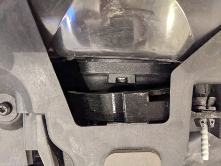
- Pull on off road lamp assembly housing to deform assembly to allow one of the off road lamp trunnions (see figure 3) to be pulled clear of assembly. It may be easier to use a screwdriver or needle nose pliers to help pry the lamp out
- I have found it easier to remove the side opposite of the vertical adjustment arm located on the off road lamp first
Assembly of off road lights with new brackets and SS3 round pods from Diode Dynamics
- First step confirm you have all the needed components
- 2 – 1 5/8” 10-32 SOC cap bolts
- 2 – 1 ¾” 10-32 SOC cap bolts
- 4 – 10-32 nylon lock nuts
- 4 – #10 washers
- 8 – #10 internal teeth lock washers
- 2 – Diode Dynamics SS3 round pods
- 2 – Deutsch DT Adapter wires (DT to 9006) for plug and play.
- Install new 3D printed pod bracket in to off road lamp assembly
- Insert vertical adjustment nut into rectangular hole in bracket
- Insert bracket trunnion vertical adjuster side first into trunnion mount (hole)
- Deform off road lamp assembly to push the other bracket trunnion into trunnion mount (hole). Note the brackets are somewhat flexible, so it may be easier to slightly bend the bracket to insert the trunnions.
- These trunnions are quite snug and may require some wiggling to get them to fit.
- Apply force to get the trunnions to slide in place by pushing directly on the pod support block (where the clearance hole for the bolts are located).

- Install the Deutsch DT adapter wires to the pods.
- Note there is a positive and negative on the 9006 end
- Slide pod into off road lamp assembly. The following is the trickiest part:
- Note the bolts are not perpendicular to the plane of the of the nut pocket when they are aligned properly. This means you have to be careful not to attempt to thread the nut on when it is misaligned. If you try to force the nut on when it is misaligned by turning the bolt you may stripe the nut and/or bolt and the 1-5/8” bolts is not a locally stocked item as far as I can tell.
- Note there is an orientation on the pods and we want the DT connector towards the bottom
- I have found it much easier to start with the 1-5/8” bolt located on the non vertical adjustment side.
- Place on the 1-5/8” bolt in this order: one internal teeth lock washer, one standard washer and one internal teeth lock washer.
- Insert the 1-5/8” bolt into bracket and use it to align the pod in roughly the correct location by aligning the bolt to the clearance hole in the pod.
- Note that the bracket can be rotated somewhat independently to the pod. For the time being try to keep the front plane of the bracket roughly parallel to the front of the pod. Avoid having the center support contacting the DT connector.
- Note we will index the pod relative to the bracket after the bolts are both started to locate the center support into the correct location
- Drop the 10-32 nylon locking nut into the pocket on the pod using a needle nose pliers
- Note orientation of the nut they need to be threads out
- This has been the hardest part of the assembly, however; I believe I have found a way to make it much easier.
- Note how the bracket where it will contacts the pod (pod support block) is not perpendicular to the bolt. In order for the nut to align correctly we want to rotate the pod about the 1-5/8” bolt side down (if looking at the back of the pod/assembly) such that the bolt and the plane where the nut is are perpendicular. This will create about an 1/8”gap between the pod support block and the pod at the top and contact at the bottom, see figure 4.

- By hand push the bolt into the lock nut and turn the bolt to start the nut. It will spin on freely if well aligned do not force on, if it immediately gets hard to turn it is misaligned.
- It may be easier to align the nut and bolt by turning the assembly such that the bolt is vertical in orientation.
- Once bolt is started turn several revolutions, but make sure it is not fully seated. We want both bolts started before they are tightened down. (Do not fully thread the lock nut until the rest of the assembly is finished and alignment checked. Lock nuts loose holding power each time they are reused).
- Repeat for 1-3/4” bolt on vertical adjustment side
- Place on the 1-3/4” bolt in this order: one internal teeth lock washer, one standard washer and one internal teeth lock washer.
- Insert the 1-3/4” bolt into bracket and use it to align the pod in roughly the correct location by aligning the bolt to the clearance hole in the pod.
- I have not had an issue starting this nut as compared to the 1-5/8” bolt side
- Drop the 10-32 nylon locking nut into the pockets on the pod using a needle nose pliers
- Note orientation of the nut they need to be threads out
- By hand push the bolt into the lock nut and turn the bolt to start the nut. It will spin on freely if well aligned do not force on, if it immediately gets snug it is misaligned.
- Once bolt is started turn several revolutions, but make sure it is not fully seated. We want both bolts started before they are tightened down. (Do not fully thread the lock nut until the rest of the assembly is finished and alignment checked. Lock nuts loose holding power each time they are reused).
- Install vertical alignment bolt by threading it into vertical alignment nut
- Once threaded on sufficiently far you can press on the bolt to lock it into the off road lamp assembly
- Align the center support.
- Rotate pod relative to bracket to locate the center support where it will contact the pod body, this will be on the black aluminum part of the pod, between the DT connecter area and the front of the pod.
- Test fit off road lamp assemblies in the off road assembly
- Take a look at how they are aligning try to make sure the orientation of the bracket to the pod looks close to Figure 4 and Figure 5
- Also note how far the vertical adjustment bolt is threaded into the vertical adjustment nut. We want to make sure you will be able to adjust the vertical angle of the light to the correct level once installed on the Xterra.
- Once happy with the general alignment, tighten the 4 10-32 bolts, I don’t have a torque spec on this as it is too low for my wrench. I’ll work on getting a spec here shortly. It is probably only a 10-15 Inch-pounds (not very tight)
- Note inserting a small flathead screwdriver to pin the nut from rotating may make it easier to tighten
- Reassembly off road assembly
- Connect the new pods via the DT adapters to the stock wiring. Make sure you get the orientations correct. My positive wires were white and purple/blue the blacks wires were the negatives.
- Connect the power harness and test pods before bolting everything back down
- Done
